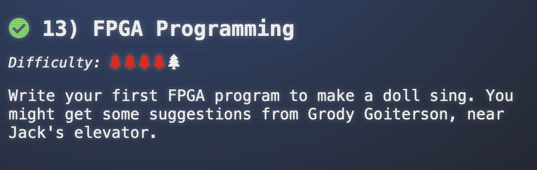
13 - FPGA Programming
This is challenge number 13 in the 2021 SANS Holiday Hack Challenge (https://2021.kringlecon.com/). Objective:
Write your first FPGA program to make a doll sing. You might get some suggestions from Grody Goiterson, near Jack’s elevator.
Exercise #4 Objective: Students must prove their design before being allowed to program an actual device. The student’s model must produce a 500Hz, 1KHz, and 2KHz square wave accurately AND accurately produce a square wave of a randomly chosen frequency. This tool will run the model under simulation, passing it the appropriate register values and measuring the frequency of the resulting square wave.
Important: Students MUST perform all simulation tests with the SAME code. If the code is changed, all tests will need to be re-run.
To get started on this challenge, I listened to Prof. Qwerty Petabyte’s awesome talk on FPGA Design for Embedded Systems https://www.youtube.com/watch?v=GFdG1PJ4QjA. I had never touched Verilog or looked into FPGA designs prior to the challenge, so fortunately I was able to start by taking the professors blinking light code snippet from their presentation.
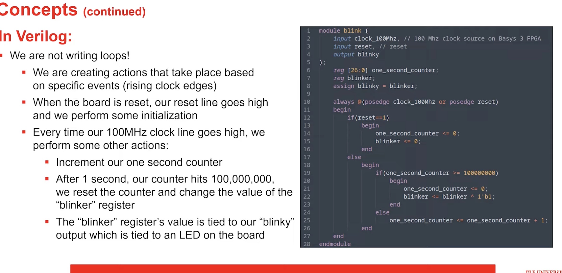
This code was a good start, but needed to be tweaked. First, I had to increase the size of the counter to 32bits
reg [31:0] counter;Secondly, we were working with a 125Mhz system clock so rather than a 100Mhz clock. So instead of using 100000000, we had to use 125000000 cycles per second in our equation. The second problem was ensuring that when building the clock divider code that it would output at a 50% duty cycle at all frequencies. Luckily, fpga4fun (https://www.fpga4fun.com/MusicBox1.html) explained that this could be done by adding a stage that first divides the output by 2.
Another important detail was how the frequency was being formatted. In the description it tells us that 9876.54Hz would be represented as 32’hf1206 or 32’d987654.
// input freq - a 32 bit integer indicating the required frequency
//              (0 - 9999.99Hz) formatted as follows:
//              32'hf1206 or 32'd987654 = 9876.54Hz
This meant that they were multiplying by 100 in order to not lose track of the decimal. So the solution needed to divide by 100 before being able to start producing a square wave.
if (counter >= (125000000/(freq/100)/2))
          begin
           counter <= $rtoi(freq) - 1;
           wave_out_reg <= 1'b1;
end
Putting it all together:
// Note: For this lab, we will be working with QRP Corporation's CQC-11 FPGA.
// The CQC-11 operates with a 125MHz clock.
// Your design for a tone generator must support the following
// inputs/outputs:
// (NOTE: DO NOT CHANGE THE NAMES. OUR AUTOMATED GRADING TOOL
// REQUIRES THE USE OF THESE NAMES!)
// input clk - this will be connected to the 125MHz system clock
// input rst - this will be connected to the system board's reset bus
// input freq - a 32 bit integer indicating the required frequency
//              (0 - 9999.99Hz) formatted as follows:
//              32'hf1206 or 32'd987654 = 9876.54Hz
// output wave_out - a square wave output of the desired frequency
// you can create whatever other variables you need, but remember
// to initialize them to something!

`timescale 1ns/1ns
module tone_generator (
    input clk,
    input rst,
    input [31:0] freq,
    output wave_out
);
    // ---- DO NOT CHANGE THE CODE ABOVE THIS LINE ----
    // ---- IT IS NECESSARY FOR AUTOMATED ANALYSIS ----

     reg [31:0] counter;
     reg wave_out_reg;
     assign wave_out = wave_out_reg;

     always @(posedge clk or posedge rst)
       begin
       if (rst == 1)
        begin
          counter <= 0;
          wave_out_reg <= 0;
       end
    else
      begin
         if (counter >= (125000000/(freq/100)/2))
           begin
            counter <= $rtoi(freq) - 1;
            wave_out_reg <= 1'b1;
       end
     else
    counter <= counter + 1;
end
end
endmodule
500Hz frequency
Sending code for analysis...
Verilog parsed cleanly...
Beginning FPGA simulation. This may take a few seconds...
Congratulations!
Simulation results indicate a frequency of exactly: 500.0000Hz
1KHz frequency
Sending code for analysis...
Verilog parsed cleanly...
Beginning FPGA simulation. This may take a few seconds...
Congratulations!
Simulation results indicate a frequency of exactly: 1000.0000Hz
2KHz frequency
Sending code for analysis...
Verilog parsed cleanly...
Beginning FPGA simulation. This may take a few seconds...
Congratulations!
Simulation results indicate a frequency of exactly: 2000.0000Hz
Simulate random
Sending code for analysis...
Verilog parsed cleanly...
Beginning FPGA simulation. This may take a few seconds...
Random target frequency: 2526.14
Using a clock frequency of 125MHz, the closest you could get to the target frequency is 2526.1711
Simulation results indicate a frequency of: 2526.0690Hz
Your square wave's frequency is within 0.004042% of the best-fit value.
Finally, program the device!
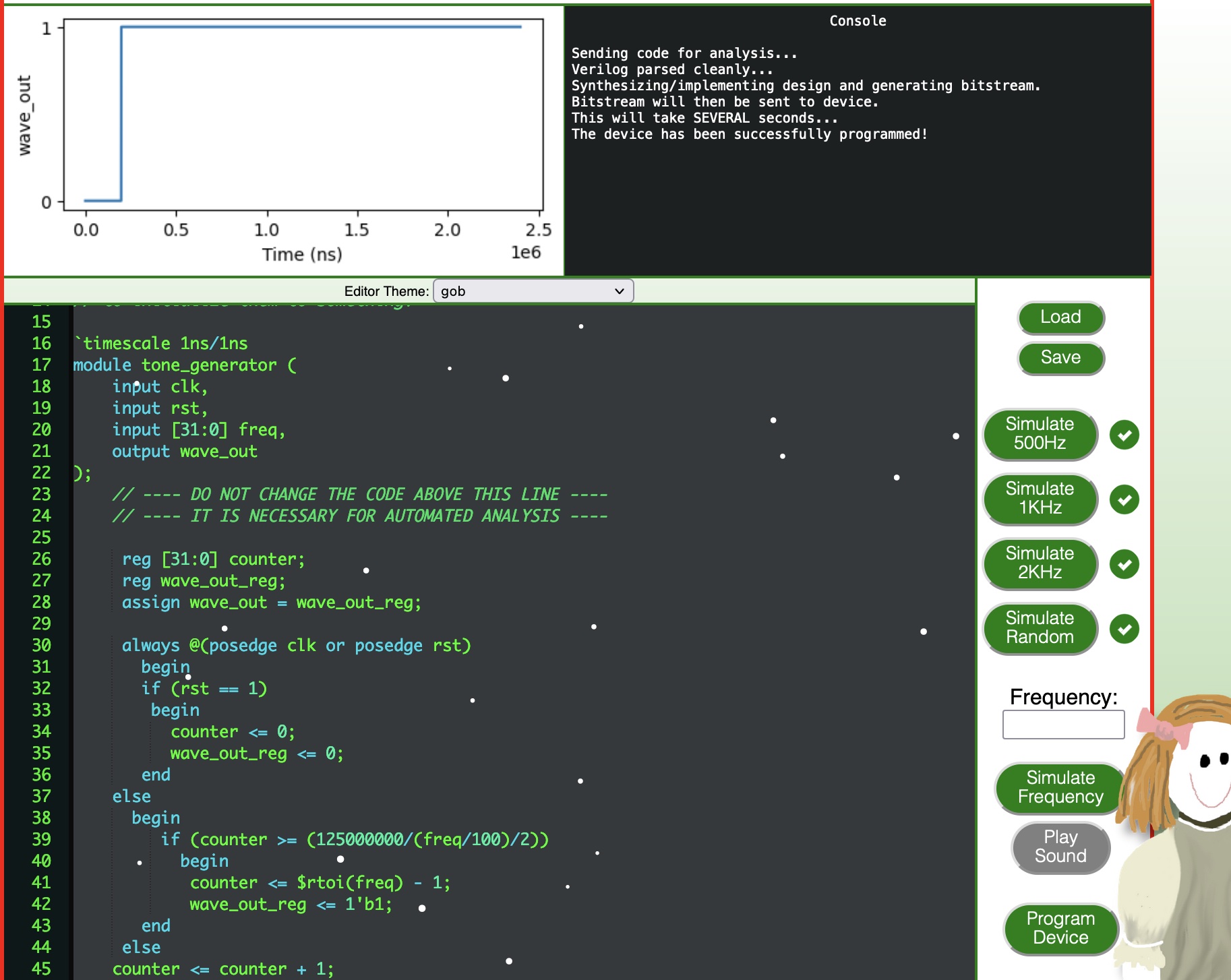
Sending code for analysis...
Verilog parsed cleanly...
Synthesizing/implementing design and generating bitstream.
Bitstream will then be sent to device.
This will take SEVERAL seconds...
The device has been successfully programmed!